- English
- Español
- Português
- русский
- Français
- 日本語
- Deutsch
- tiếng Việt
- Italiano
- Nederlands
- ภาษาไทย
- Polski
- 한국어
- Svenska
- magyar
- Malay
- বাংলা ভাষার
- Dansk
- Suomi
- हिन्दी
- Pilipino
- Türkçe
- Gaeilge
- العربية
- Indonesia
- Norsk
- تمل
- český
- ελληνικά
- український
- Javanese
- فارسی
- தமிழ்
- తెలుగు
- नेपाली
- Burmese
- български
- ລາວ
- Latine
- Қазақша
- Euskal
- Azərbaycan
- Slovenský jazyk
- Македонски
- Lietuvos
- Eesti Keel
- Română
- Slovenski
- मराठी
- Srpski језик

Our New Product-300W GaN Power Supply
2026-04-22
STARWELL is a high-tech enterprise specializing in power supply manufacturing, committed to the R&D and production of various advanced power supply products, including POE power supplies, communication power supplies, energy storage inverters, power adapters, industrial control power supplies, etc., to meet the needs of different fields. This issue's solution analysis brings a 300W 48V GaN power supply module.
The model of this power supply module is R0168, supporting an input voltage of 100~264Vac, with an output of 48V 6.25A and an output power of 300W. It can operate in an ambient temperature range of -10~55℃. The power supply features a modular design, with connectors provided at both the input and output terminals. The following is a solution analysis of this 300W GaN power supply module, to take a look at its internal design and materials.
Appearance of STARWELL 300W GaN Power Supply
Module
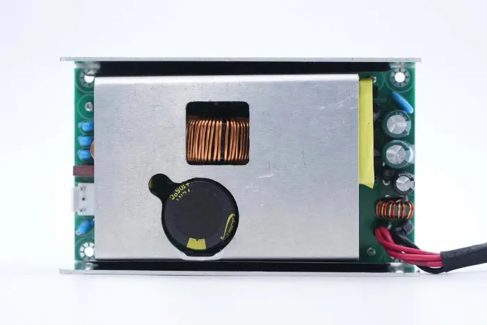
The STARWELL 300W GaN power supply module adopts an aluminum alloy shell. The front of the PCBA module is equipped with an aluminum alloy heat sink, with hollowed-out areas corresponding to the high-voltage filter capacitors and PFC boost inductor to reduce thickness.
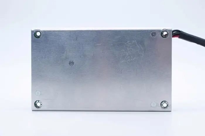
The back of the power supply module is an aluminum alloy shell.
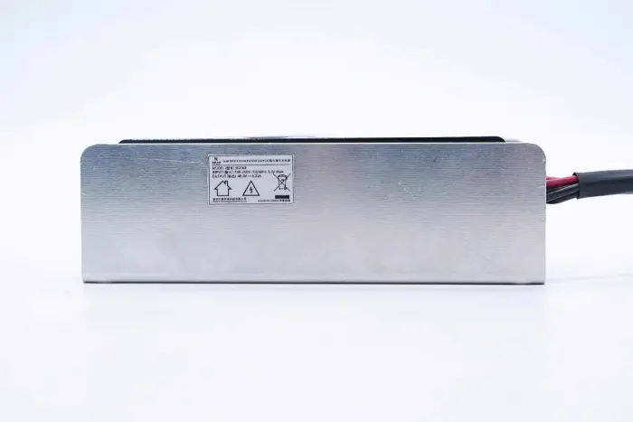
Model: B0168
Input: 100-240V~ 50/60Hz 5.0A Max
Output: 48V 6.25A
The output wires are connected by soldering, with heat-shrink tubing sleeved on the solder joints for insulation.

Close-up of the output connector: the red wire is the positive pole, and the sleeve is marked for 48V output.

The length of the power supply module measured with a vernier caliper is approximately 127.1mm.

The width of the power supply module is approximately 76.4mm.

The thickness of the power supply module is approximately 40.4mm.

Intuitive size perception of the power supply module held in hand. Thanks to the use of GaN power devices, the power density is greatly improved, and the volume of 300W output power is significantly reduced, saving space.
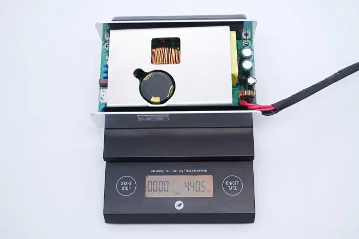
The measured weight of the power supply module is approximately 441g.
Analysis of STARWELL 300W GaN Power Supply
Module
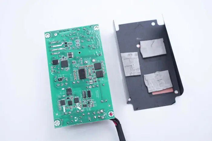
The PCBA module is fixed to the heat sink with screws.
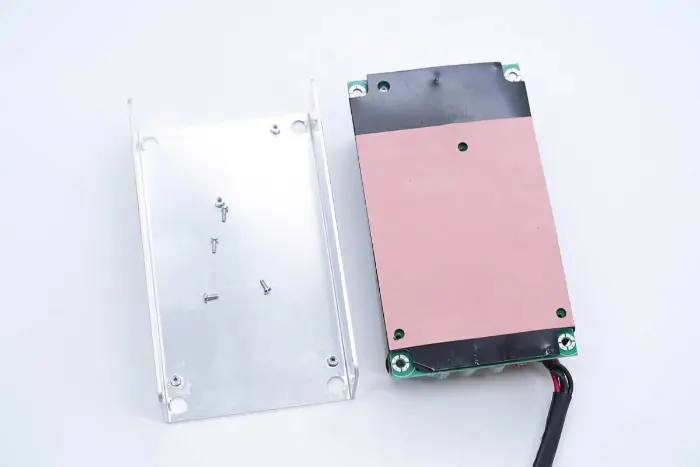
Insulating silicone sheets are pasted at positions corresponding to the heat sink when the PCBA module is taken out.
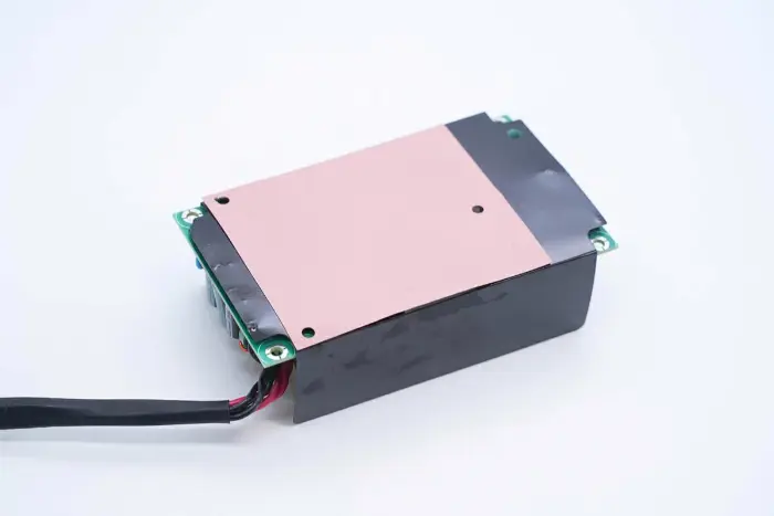
An insulating Mylar sheet is provided on the side of the PCBA module.
The insulating Mylar sheet is removed, with holes cut at positions corresponding to power devices, and thermal pads are provided to conduct heat.
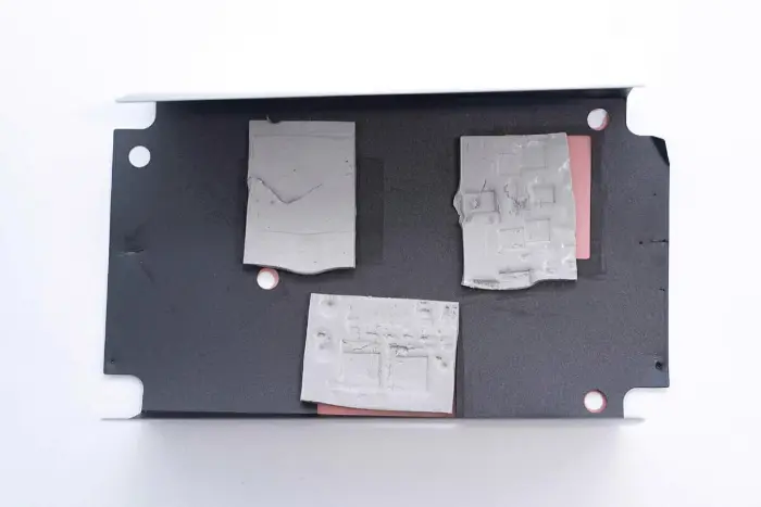
Three thermal pads correspond to the PFC switch, LLC switch, and synchronous rectifier respectively.
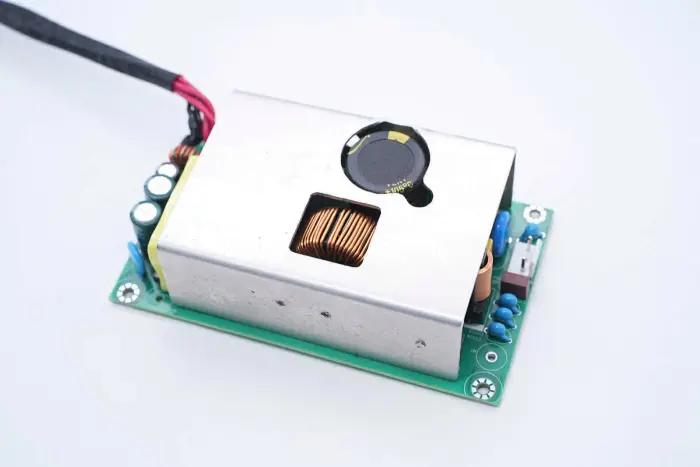
An aluminum alloy heat sink is also covered on the PCBA module, and power devices are fixed with screws.
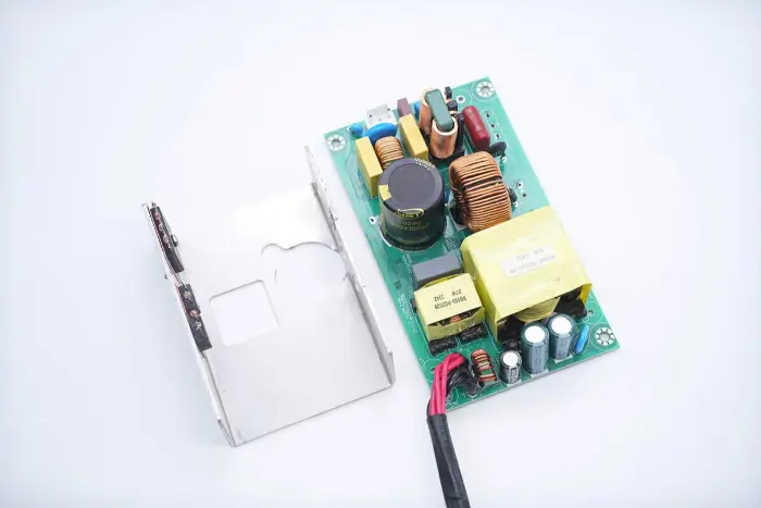
The heat sink covered on the PCBA module is removed by desoldering.
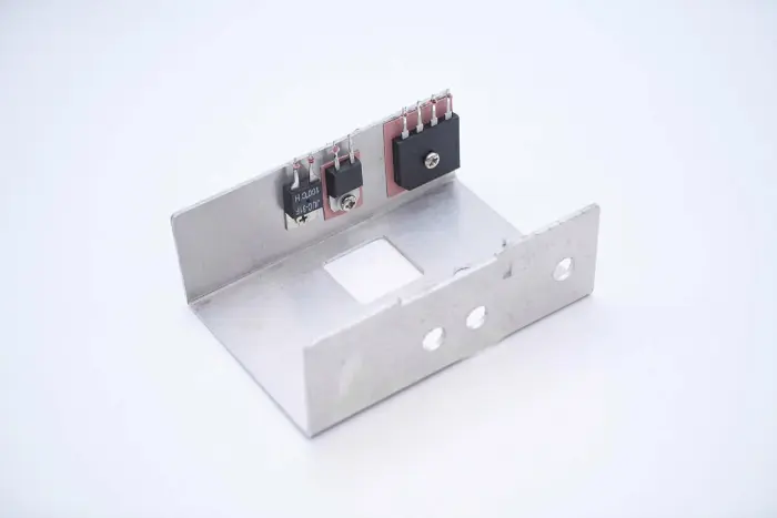
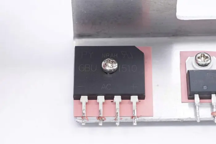
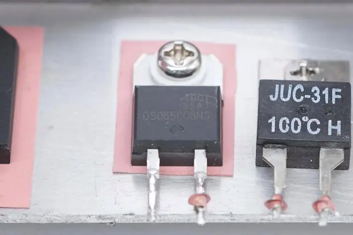
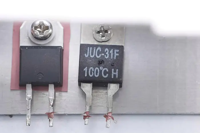
The rectifier bridge, PFC rectifier diode, and thermal switch are fixed on the heat sink.
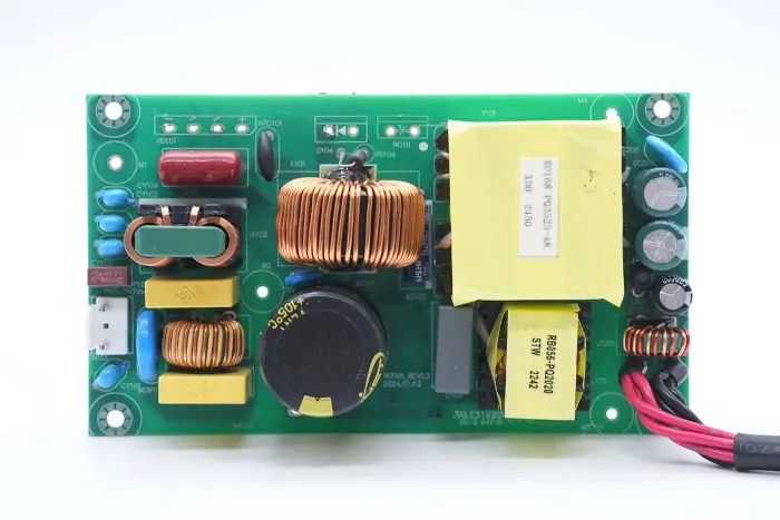
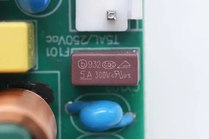
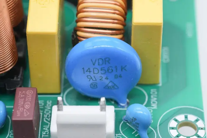
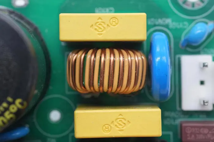
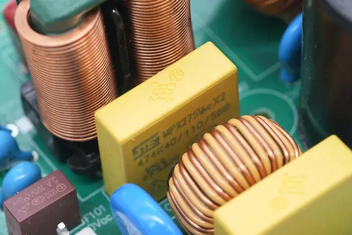
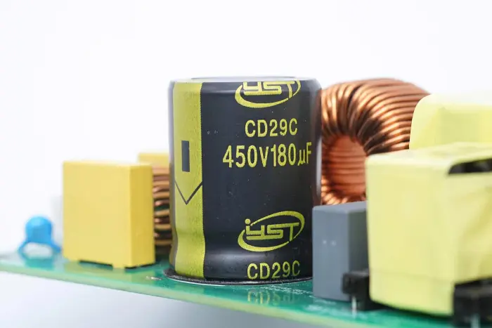
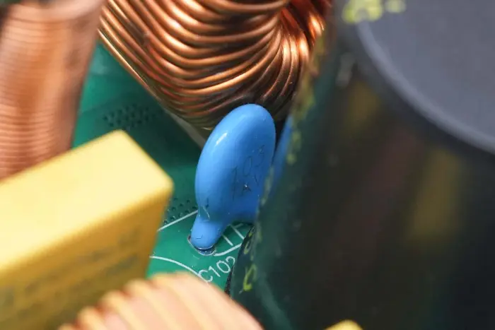
Overview of the front of the PCBA module: the left side is equipped with a power input socket, fuse, Y capacitor, varistor, common-mode inductor, and safety X2 capacitor. The middle position is equipped with a PFC boost inductor and high-voltage filter capacitor. The right side is equipped with LLC resonant capacitor, resonant inductor, transformer, filter capacitor, and filter inductor.
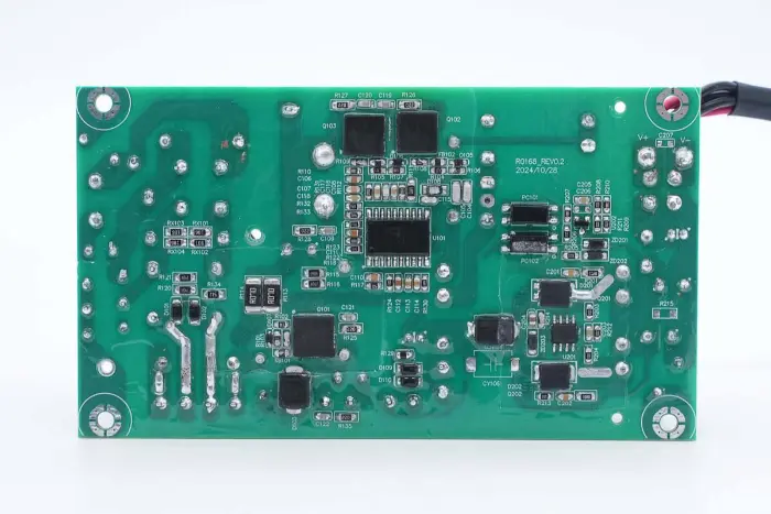
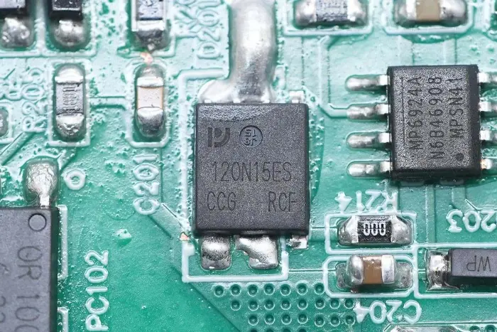
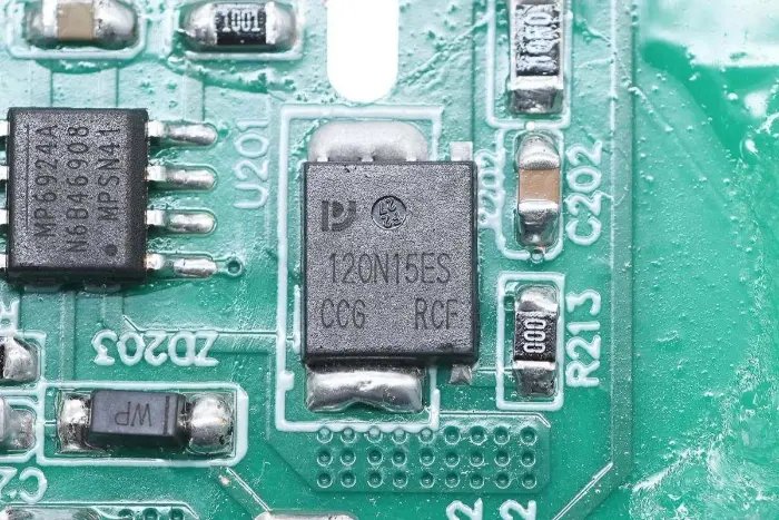
On the back of the PCBA module, there is a 2-in-1 PFC+LLC controller. The PFC switch is located at the lower left, the LLC switch is above the main control chip, the feedback optocoupler is on the right, and the synchronous rectifier controller and two synchronous rectifiers are at the bottom. The whole board is coated with conformal coating for protection.
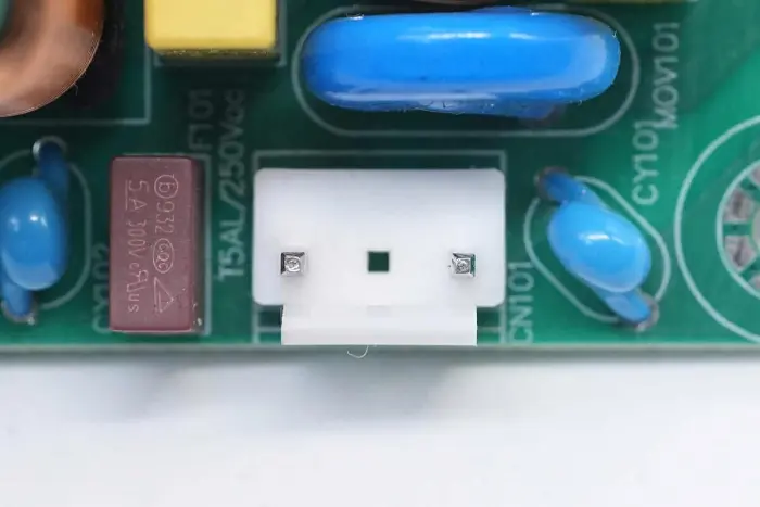
The AC input terminal is connected with a connector.
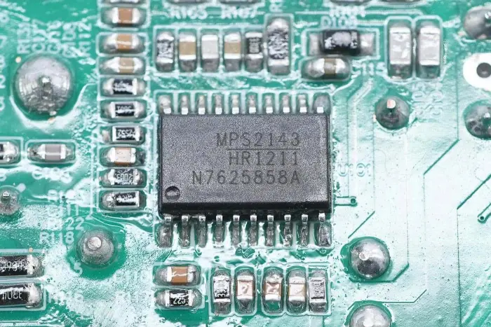
The main control chip of the power supply adopts Mornsun Semiconductor HR1211, a multi-mode PFC and current-mode LLC 2-in-1 controller. It integrates functions that require 2-3 chips in traditional solutions into one chip. The PFC controller supports CCM and DCM operating modes.
HR1211 adopts a digital control core, supports high-voltage startup and intelligent X capacitor discharge. The PFC stage supports a maximum operating frequency of 250KHz. The LLC stage has a built-in 600V half-bridge driver with integrated bootstrap diode, operating at a frequency up to 500KHz. It supports comprehensive protection functions and is packaged in SOIC-20.
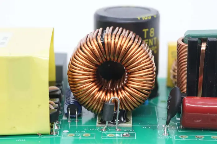
The PFC boost inductor is wound with a magnetic ring, and a bakelite sheet is provided at the bottom for insulation.
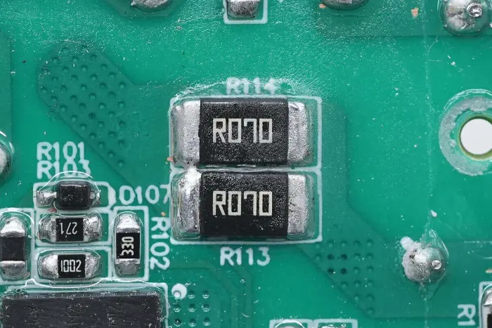
Two 70mΩ resistors are connected in parallel to detect the switch current.
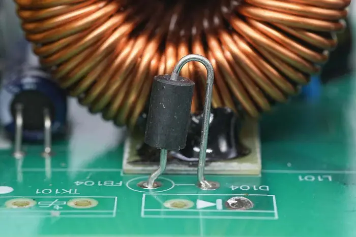
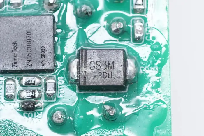
The PFC rectifier diode is connected in series with a magnetic bead.
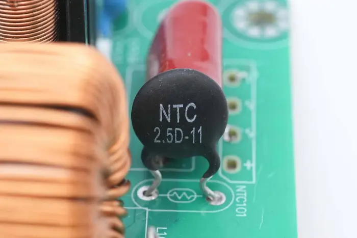
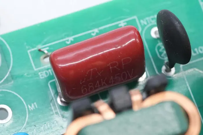
The NTC thermistor is marked 2.5D-11, used to suppress the charging current of the high-voltage electrolytic capacitor.
Ceramic capacitors are connected in parallel with electrolytic capacitors, with a specification of 0.01μF 1KV.
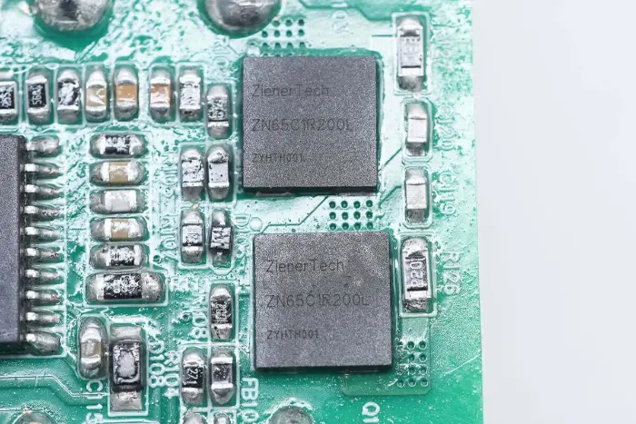
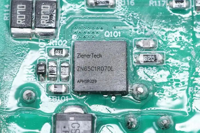
The LLC switch is from ZenerTech, model ZN65C1R200L, a Cascode structure GaN switch with a withstand voltage of 700V and transient withstand voltage of 800V, on-resistance of 200mΩ, gate drive voltage support of 20V. It features low gate charge, effectively simplifying the drive circuit. Suitable for fast chargers, communication power supplies, data centers, and lighting applications, packaged in DFN8*8.
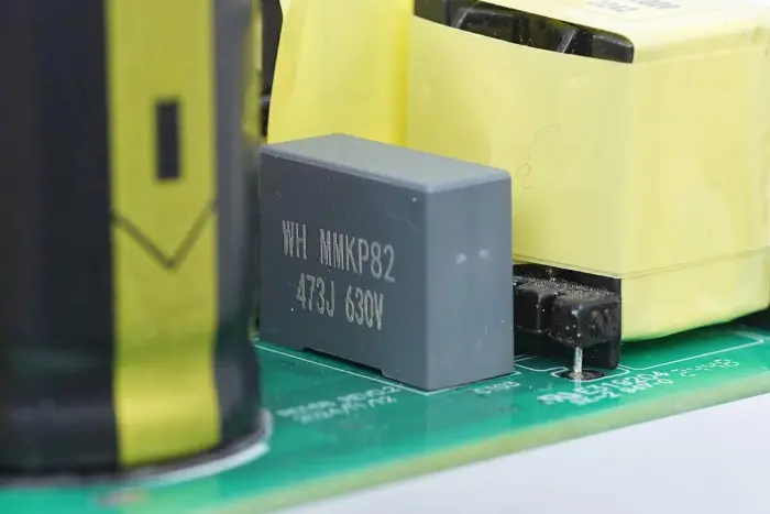
The resonant capacitor is of MMKP82 series, with a specification of 0.047μF 630V.
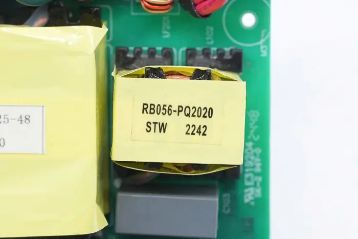
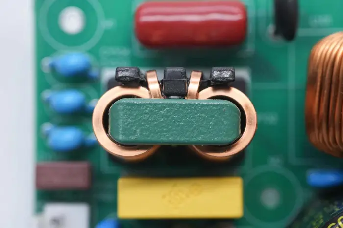
The resonant inductor adopts PQ2020 magnetic core and is wound with litz wire.
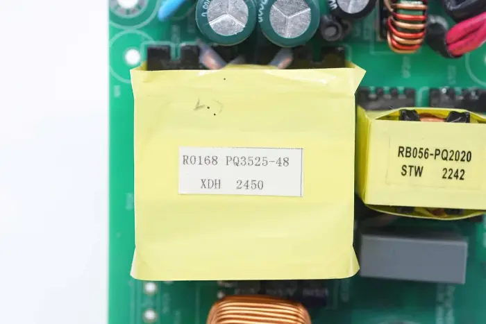
The transformer adopts PQ3525 magnetic core, marked with power supply model R0168.
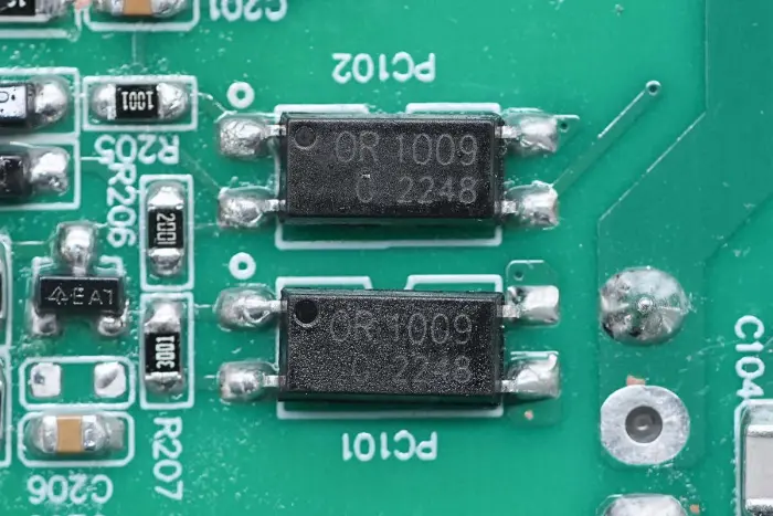
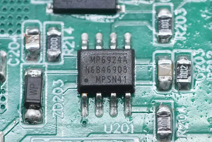
The synchronous rectifier controller is from MPS, model MP6924A, an LLC synchronous rectifier controller with stronger anti-interference and fast turn-off functions, compatible with CCM/DCM modes. MP6924A integrates two synchronous rectifier controllers for rectification applications of the two secondary coils of LLC, suitable for LLC converter synchronous rectification applications, packaged in SOIC-8.
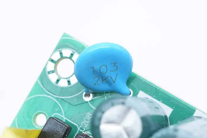
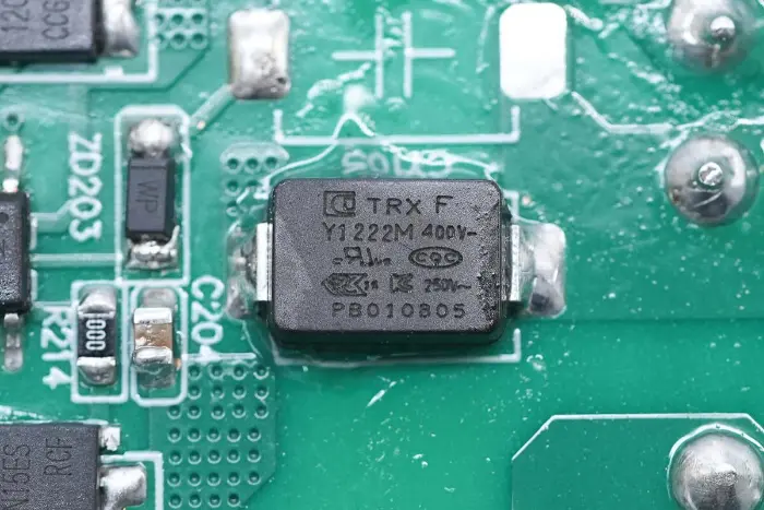
A ceramic capacitor is connected between the output terminal and ground, with a specification of 0.01μF 2KV.
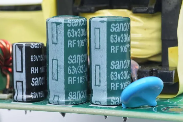
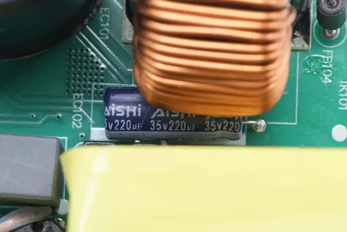
The output filter capacitors are from Sancon (Nantong Sanxin), RF series long-life capacitors, with a specification of 63V 330μF, two in parallel.

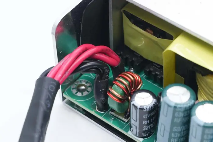
The filter inductor is sleeved with heat-shrink tubing for insulation.
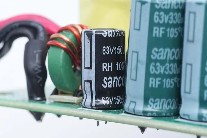
Another filter capacitor has a specification of 63V 150μF.

Close-up of the output magnetic ring filter inductor.
Summary
Through analysis, it is found that the 300W GaN power supply module launched by STARWELL uses through-hole rectifier bridges and rectifier diodes fixed on the internal heat sink. Patch GaN switches use thermal pads to conduct heat to the bottom aluminum alloy shell for heat dissipation, improving heat dissipation capacity. A thermal switch is installed on the internal heat sink to switch the controller power supply in case of overheating, realizing overall overheating protection.
This GaN power supply module adopts Mornsun Semiconductor control solution, using HR1211 2-in-1 controller with MP6924A synchronous rectifier controller. The PFC switch adopts ZenerTech ZN65C1R070L GaN switch, PFC rectifier diode adopts Sanken SDS065J008N3 SiC diode, and LLC switch adopts ZN65C1R200L GaN switch. The third-generation semiconductors are used to improve power conversion efficiency, reduce power loss and heat dissipation requirements.